QUINT-PS/3AC Schaltnetzteile 3-Phasig für Hutschienenmontage
Robust mit SFB (Selective Fuse Breaking) Technology & NFC
- Ausgangsspannung: 24 oder 48 V DC
- Verstellbare Ausgangsspannungsbereiche: 18 bis 56 V-DC
- Ausgangs-Ampere: 10, 20 oder 40 Amp
- Ausgangsleistung: 240, 480 oder 960 W
- Eingangsspannungsbereiche: 3-phasig oder 2-phasig AC oder DC
QUINT 3-phasige Stromversorgungen bieten eine Reihe von robusten AC/DC- und DC/DC-Wandlern, die die hohen Stabilitäts- und Effizienzerwartungen der Bereiche Industrie, Maschinenautomation und Prozesskontrolle erfüllen. Sie verfügen außerdem über die einzigartige Kombination aus präventiver Funktionsüberwachung und Leistungsreserve in einer unglaublich kompakten Größe. Diese Schaltnetzteile, die perfekt für die Anwendung in Hochleistungsanwendungen geeignet sind, sorgen für eine regulierte Ausgangsspannung, selbst wenn es im Stromnetz zu Spannungsschwankungen kommen sollte. Im Parallelbetrieb sowie beim Anschluss an verschiedene Phasen werden die Lasten zuverlässig versorgt, selbst wenn es zu Problemen mit der Eingangsspannung kommen sollte. Die QUINT Stromversorgungen verfügen über alle zur Unterstützung von ITE (informationstechnische Geräte) erforderlichen Sicherheitszertifikate, eine robuste Verpackung, erweiterte Betriebstemperaturbereiche, hohe Spitzenlasten und hohe Isolationsspannungen und können dadurch die Anforderungen Ihrer industriellen Anwendung erfüllen.
POWER BOOST: zuverlässiger Start von schwierigen Lasten

Bei der Konfiguration, Optimierung und Erweiterung von großen Systemen ist viel Flexibilität gefragt. Eine Leistungsreserve in der Stromversorgungseinheit ist wichtig, um ein System oder eine Maschine optimal an Ihre Anforderungen anzupassen. Die QUINT bietet bis zu 50% zusätzlichen Strom ohne Spannungsabfall. Das ist dann nützlich, wenn nicht vorhergesagt werden kann, welche Lasten zur gleichen Zeit eingeschaltet werden, oder wenn hohe Einschaltströme von kapazitiven Lasten ohne Spannungsabsenkungen absorbiert werden müssen. Mit der QUINT Power-Boost-Funktion liefert ein statischer Boost kontinuierlich bis zu 125% des Nennstroms. Außerdem können Sie beim Starten schwerer Lasten durch den dynamischen Boost 5 Sekunden lang bis zu 200% des Nennstroms nutzen.
Präventive Funktionsüberwachung meldet kritische Betriebszustände, bevor sie auftreten

Mit einer QUINT Stromversorgung werden die Ausgangsspannung und der Ausgangsstrom ständig überwacht. Die präventive Funktionsüberwachung visualisiert kritische Betriebszustände an und zeigt sie dem Controller folgendermaßen sowohl lokal als auch auf Entfernung an:
- Über LED
- Über potentialfreien Relaiskontakt
- Über aktiven Schaltausgang
Industrielle Betriebstemperatur von -25°C bis +70°C
Geräte in den Bereichen Verkehrsmanagement, Öl- und Gaspipelines, Wetterverfolgung, industrielle und Outdoor-Anwendungen müssen bei Temperaturen funktionsfähig bleiben, die von kommerziellen Stromversorgungen nicht getragen werden. Bei einer Betriebstemperatur von -25°C bis +70°C und einer zuverlässigen Inbetriebnahme des Geräts bei -40°C ist die QUINT Stromversorgung ideal für Geräte, die rauen Umgebungen und extremen Temperaturen ausgesetzt sind.
Hohe Effizienz und niedrige Leistungsaufnahme bei Nulllast
Im Vergleich zu anderen Produkten auf dem Markt bietet die QUINT Stromversorgung hervorragende Energieeinsparungen. Dank der sehr niedrigen Leistungsaufnahme bei Nulllast und hoher Effizienz bei Nennlast wird nur eine geringe Menge an elektrischer Energie in unerwünschte Wärmeenergie umgewandelt, wodurch diese Stromversorgungen besonders umweltfreundlich sind.

SFB (Selective Fuse Breaking)-Technology an ausgewählten Modellen
SFB-Technology wird verwendet, um schnell und zuverlässig Miniaturtrennschalter und sekundärseitig angeschlossene Sicherungen auszulösen. Im Falle eines Kurzschlusses an der sekundären Seite liefert QUINT bis zu 15 ms lang den bis zu 6-fachen Nennstrom. Fehlerhafte Strompfade werden gezielt ausgeschaltet, der Fehler wird behoben und wichtige Systemteile bleiben in Betrieb. Parallel angeschlossene Lasten werden weiter mit Energie versorgt, was den fortlaufenden Betrieb dieser Systemteile gewährleistet.
- Auslösen von Trennschaltern: Der Trennschalter wird für gewöhnlich innerhalb von 3 bis 5 ms von dem hohen SFB-Strom ausgelöst. Dadurch werden bei parallel angeschlossenen Lasten Spannungsabsenkungen vermieden.
- Auslösen einer Sicherung: Sicherungen werden ausgelöst, indem die Sollbruchstelle in der Sicherungskapsel geschmolzen wird. Die Auslösekennlinie der Sicherung wird durch den Schmelzintegral (I²t) beschrieben. Ein Hochstrom ist für eine sehr kurze Auslösezeit ausschlaggebend.

Near Field Communication (Nahfeldkommunikation, NFC) an ausgewählten Modellen
Die Near Field Communication (NFC) ist ein Übertragungsstandard für drahtlosen und kontaktlosen Datenaustausch aus nächster Nähe. Mit NFC können Sie QUINT-Stromversorgungseinstellungen einfach parametrisieren, zum Beispiel die Definition von Meldeschwellen für die präventive Funktionsüberwachung, Angleichung der Ausgangsspannung und Anpassung der Ausgangskennlinie an Ihre spezifischen Anforderungen mit einem PC, einem Mobiltelefon oder einem mobilen Endgerät. Außerdem können Sie Konfigurationsprofile auf Ihrem mobilen Endgerät speichern und versenden. QUINT Power NFC App im Google Play Store.
Ideale Anwendungsumgebungen für QUINT 3-Phasge Schaltnetzteile für Hutschienenmontage:
- Antriebsmotoren und andere Geräte
- Maschinenbau
- Automatisierter Produktionsablauf
- Industriesteuerung, Automatisierung, Montage und Prüfgeräte
- Baukontrolle, Sicherheit und Überwachung und Klimaanlagen.
- Stromversorgung von vielen Industrieautomatisierungsgeräten wie Sensoren, Controllern und Ventilen
Weitere Gründe sich für QUINT 3-Phasige Stromversorgungen zu entscheiden:
- Robuste Eingangsseite: hohe Störimmunität durch integrierten Gasableiter (bis 6 kV) und ≥ 20 ms Netzausfall-Überbrückungszeit
- Schmales, schlankes Design spart Platz im Schaltkasten
- Spannungsisolierung Eingang/Ausgang: 4 kV-AC
- Schutzvorkehrungen: Kurzschluss, Überlast, Überspannung, Übertemperatur
- Hohe MTBF (mittlerer Ausfallabstand)-Werte
Environmental Product Compliance
REACH SVHC
23208278
Lead 7439-92-1
28668028
Lead 7439-92-1
29046218
Lead 7439-92-1
29046228
Lead 7439-92-1
China RoHS
Environmentally Friendly Use Period = 25;
General
Net weight
23208278
2.5 kg
28668028
2.5 kg
29046218
0.9 kg
29046228
1.1 kg
Efficiency
23208278
> 93 % (at 400 V AC and nominal values)
28668028
> 94 % (at 400 V AC and nominal values)
29046218
typ. 93 % (400 V AC)
29046228
typ. 93.9 % (400 V AC)
Insulation voltage input/output
23208278
- 4 kV AC (type test)
- 2 kV AC (routine test)
28668028
- 4 kV AC (type test)
- 2 kV AC (routine test)
29046218
- 4 kV AC (type test)
- 2.4 kV AC (routine test)
29046228
- 4 kV AC (type test)
- 2.4 kV AC (routine test)
Insulation voltage input / PE
23208278
- 3.5 kV AC (type test)
- 2 kV AC (routine test)
28668028
- 3.5 kV AC (type test)
- 2 kV AC (routine test)
29046218
- 3.5 kV AC (type test)
- 2.4 kV AC (routine test)
29046228
- 3.5 kV AC (type test)
- 2.4 kV AC (routine test)
Insulation voltage output / PE
23208278
500 V DC (routine test)
28668028
500 V DC (routine test)
29046218
0.5 kV DC (type test)
29046228
0.5 kV DC (type test)
Protection class
I
Degree of protection
IP20
MTBF (IEC 61709, SN 29500)
23208278
889679,72 h (25°C)
501504,51 h (40°C)
216825,67 h (60°C)
28668028
> 880000 h (25°C)
> 500000 h (40°C)
> 216000 h (60°C)
29046218
> 1034000 h (25°C)
> 654000 h (40°C)
> 320000 h (60°C)
29046228
> 985000 h (25°C)
> 638000 h (40°C)
> 311000 h (60°C)
Mounting position
horizontal DIN rail NS 35, EN 60715
Assembly instructions
alignable: PN ≥50%,
5 mm horizontally
15 mm next to active components
50 mm vertically alignable: PN <50%
0 mm horizontally
40 mm vertically top
20 mm vertically bottom
Operating voltage display
23208278
28668028
Green LED
29046218
29046228
Efficiency
23208278
28668028
29046218
typ. 92.6 % (480 V AC)
29046228
typ. 93.8 % (480 V AC)
Insulation voltage output / PE
23208278
28668028
29046218
0.5 kV DC (routine test)
29046228
0.5 kV DC (routine test)
Standards and Regulations
Electromagnetic compatibility
Conformance with EMC Directive 2014/30/EU
Noise immunity
23208278
EN 61000-6-2:2005
28668028
EN 61000-6-2:2005
29046218
Immunity according to EN 61000-6-1 (residential), EN 61000-6-2 (industrial), and EN 61000-6-5 (power station equipment zone), IEC/EN 61850-3 (energy supply)
29046228
Immunity according to EN 61000-6-1 (residential), EN 61000-6-2 (industrial), and EN 61000-6-5 (power station equipment zone), IEC/EN 61850-3 (energy supply)
Connection in acc. with standard
23208278
CSA
28668028
CSA
29046218
29046228
Standards/regulations
EN 61000-4-2
Contact discharge
4 kV (Test Level 2)
Standards/regulations
EN 61000-4-3
Frequency range
80 MHz ... 1 GHz
Test field strength
10 V/m (Test Level 3)
Frequency range
1.4 GHz ... 2 GHz
Test field strength
3 V/m (Test Level 2)
Standards/regulations
EN 61000-4-4
Comments
Criterion B
Standards/regulations
23208278
EN 61000-4-6
28668028
EN 61000-6-3
29046218
EN 61000-4-6
29046228
EN 61000-4-6
Frequency range
0.15 MHz ... 80 MHz
Voltage
10 V (Test Level 3)
Low Voltage Directive
23208278
Conformance with LV directive 2006/95/EC
28668028
Conformance with LV directive 2006/95/EC
29046218
Conformance with Low Voltage Directive 2014/35/EC
29046228
Conformance with Low Voltage Directive 2014/35/EC
Standard - Safety of transformers
23208278
IEC 61558-2-17
28668028
29046218
EN 61558-2-16 (air clearances and creepage distances only)
29046228
EN 61558-2-16 (air clearances and creepage distances only)
Standard - Electrical safety
IEC 60950-1/VDE 0805 (SELV)
Standard – Electronic equipment for use in electrical power installations and their assembly into electrical power installations
23208278
EN 50178/VDE 0160 (PELV)
28668028
EN 50178/VDE 0160 (PELV) / Overvoltage category III
29046218
EN 50178/VDE 0160 (PELV)
29046228
EN 50178/VDE 0160 (PELV)
Standard - Safe isolation
DIN VDE 0100-410
Standard – Protection against shock currents, basic requirements for protective separation in electrical equipment
23208278
EN 50178
28668028
29046218
29046228
Standard – Limitation of mains harmonic currents
EN 61000-3-2
Standard - Equipment safety
23208278
BG (design tested)
28668028
GS (tested safety)
29046218
29046228
Standard - Approval for medical use
23208278
IEC 60601-1, 2 x MOOP
28668028
29046218
29046228
UL approvals
23208278
- UL/C-UL listed UL 508
- UL/C-UL Recognized UL 60950-1 (3-wire + PE, star net)
- UL ANSI/ISA-12.12.01 Class I, Division 2, Groups A, B, C, D (Hazardous Location)
28668028
- UL/C-UL listed UL 508
- UL/C-UL Recognized UL 60950-1 (3-wire + PE, star net)
- UL ANSI/ISA-12.12.01 Class I, Division 2, Groups A, B, C, D (Hazardous Location)
29046218
- UL/C-UL listed UL 508
- UL/C-UL Recognized UL 60950-1
- UL ANSI/ISA-12.12.01 Class I, Division 2, Groups A, B, C, D (Hazardous Location)
29046228
- UL/C-UL listed UL 508
- UL/C-UL Recognized UL 60950-1
- UL ANSI/ISA-12.12.01 Class I, Division 2, Groups A, B, C, D (Hazardous Location)
Shock
18 ms, 30g, in each space direction (according to IEC 60068-2-27)
Vibration (operation)
23208278
< 15 Hz, amplitude ±2.5 mm (according to IEC 60068-2-6)
15 Hz ... 150 Hz, 2.3g, 90 min.
28668028
5 Hz ... 100 Hz resonance search 2.3g, 90 min., resonance frequency 2.3g, 90 min. (according to DNV GL Class C)
29046218
5 Hz ... 100 Hz resonance search 2.3g, 90 min., resonance frequency 2.3g, 90 min. (according to DNV GL Class C)
29046228
5 Hz ... 100 Hz resonance search 2.3g, 90 min., resonance frequency 2.3g, 90 min. (according to DNV GL Class C)
Information technology equipment - safety (CB scheme)
23208278
CB Scheme
28668028
CB Scheme
29046218
29046228
Rail applications
23208278
EN 50121-4
28668028
EN 50121-4
29046218
EN 50121-3-2
29046228
EN 50121-3-2
Overvoltage category (EN 62477-1)
23208278
III
28668028
III
29046218
III (≤ 2000 m)
29046228
III (≤ 2000 m)
Standards/regulations
23208278
28668028
EN 61000-4-6
29046218
EN 61000-4-8
29046228
EN 61000-4-8
Standard - Safe isolation
23208278
28668028
DIN VDE 0106-101
29046218
29046228
Shipbuilding approval
23208278
28668028
DNV GL (EMC A), ABS, LR, RINA, NK, BV
29046218
DNV GL, PRS, BV, LR, ABS
29046228
DNV GL, PRS, BV, LR, ABS
Noise emission
23208278
28668028
29046218
Additional basic standard EN 61000-6-5 (immunity in power station), IEC/EN 61850-3 (energy supply)
29046228
Additional basic standard EN 61000-6-5 (immunity in power station), IEC/EN 61850-3 (energy supply)
Conducted noise emission
23208278
28668028
29046218
EN 55016 EN 61000-6-4 (Class A)
29046228
EN 55016 EN 61000-6-4 (Class A)
Standards/regulations
23208278
28668028
29046218
- EN 61000-4-11
- EN 61000-4-9
- EN 61000-4-12
- EN 61000-4-16
- EN 61000-4-18
29046228
- EN 61000-4-11
- EN 61000-4-9
- EN 61000-4-12
- EN 61000-4-16
- EN 61000-4-18
Standard - power supply devices for low voltage with DC output
23208278
28668028
29046218
EN 61204-3
29046228
EN 61204-3
EMC requirements, power plant
23208278
28668028
29046218
- IEC 61850-3
- EN 61000-6-5
29046228
Approval - requirement of the semiconductor industry with regard to mains voltage dips
23208278
28668028
29046218
SEMI F47-0706; EN 61000-4-11
29046228
SEMI F47-0706; EN 61000-4-11
Overvoltage category (EN 60950-1)
23208278
28668028
29046218
II (≤ 5000 m)
29046228
II (≤ 5000 m)
Overvoltage category (EN 61010-1)
23208278
28668028
29046218
II (≤ 5000 m)
29046228
II (≤ 5000 m)
Connection data, input
Connection method
Screw connection
Conductor cross section solid min.
0.2 mm²
Conductor cross section solid max.
6 mm²
Conductor cross section flexible min.
0.2 mm²
Conductor cross section flexible max.
4 mm²
Conductor cross section AWG min.
23208278
18
28668028
18
29046218
30
29046228
30
Conductor cross section AWG max.
10
Stripping length
23208278
7 mm
28668028
7 mm
29046218
8 mm
29046228
8 mm
Screw thread
23208278
M4
28668028
M3
29046218
29046228
Output data
Nominal output voltage
23208278
48 V DC ±1 %
28668028
24 V DC ±1 %
29046218
24 V DC
29046228
24 V DC
Setting range of the output voltage (USet)
23208278
30 V DC ... 56 V DC (> 48 V DC, constant capacity restricted)
28668028
18 V DC ... 29.5 V DC (> 24 V DC, constant capacity restricted)
29046218
24 V DC ... 29.5 V DC (constant capacity)
29046228
24 V DC ... 29.5 V DC (constant capacity)
Nominal output current (IN)
23208278
20 A (-25°C ... 60°C, UOUT = 48 V DC)
28668028
40 A (-25°C ... 60°C, UOUT = 24 V DC)
29046218
10 A
29046228
20 A
POWER BOOST (IBoost)
23208278
22.5 A (-25°C ... 40°C permanent, UOUT = 48 V DC)
28668028
45 A (-25°C ... 40°C permanent, UOUT = 24 V DC)
29046218
29046228
Selective Fuse Breaking (ISFB)
23208278
100 A (12 ms)
28668028
215 A (12 ms)
29046218
60 A (15 ms)
29046228
120 A (15 ms)
Derating
23208278
60°C ... 70°C (2.5%/K)
28668028
60°C ... 70°C (2.5%/K)
29046218
> 60°C (2.5%/K)
29046228
> 60°C (2.5%/K)
Connection in parallel
Yes, for redundancy and increased capacity
Connection in series
Yes
Feedback resistance
23208278
max. 60 V DC
28668028
max. 35 V DC
29046218
≤ 35 V DC
29046228
≤ 35 V DC
Protection against surge voltage on the output
23208278
< 60 V DC
28668028
< 35 V DC
29046218
≤ 32 V DC
29046228
≤ 32 V DC
Active current limitation
23208278
Approx. IBOOST = 22.5 A (for short-circuit)
28668028
29046218
29046228
Control deviation
23208278
- < 1 % (change in load, static 10 % ... 90 %)
- < 4 % (change in load, dynamic 10 % ... 90 %)
- < 0.1 % (change in input voltage ±10 %)
28668028
- < 1 % (change in load, static 10 % ... 90 %)
- < 3 % (change in load, dynamic 10 % ... 90 %)
- < 0.1 % (change in input voltage ±10 %)
29046218
- < 0.5 % (Static load change 10 % ... 90 %)
- < 2 % (Dynamic load change 10 % ... 90 %, (10 Hz))
- < 0.25 % (change in input voltage ±10 %)
29046228
- < 0.5 % (Static load change 10 % ... 90 %)
- < 3 % (Dynamic load change 10 % ... 90 %, (10 Hz))
- < 0.25 % (change in input voltage ±10 %)
Residual ripple
23208278
< 50 mVPP (with nominal values)
28668028
< 40 mVPP (with nominal values)
29046218
< 75 mVPP (with nominal values)
29046228
< 60 mVPP (with nominal values)
Output power
23208278
960 W
28668028
960 W
29046218
240 W
29046228
480 W
Typical response time
23208278
< 1 s
28668028
< 0.5 s
29046218
300 ms (from SLEEP MODE)
29046228
300 ms (from SLEEP MODE)
Maximum power dissipation in no-load condition
23208278
24 W
28668028
18 W
29046218
< 5 W (400 V AC)
29046228
< 7 W (400 V AC)
Power loss nominal load max.
23208278
70 W
28668028
63 W
29046218
< 19 W (400 V AC)
29046228
< 32 W (400 V AC)
Peak switching voltages nominal load
23208278
28668028
< 5 mVPP (at nominal values, 20 MHz)
29046218
29046228
Static Boost (IStat.Boost)
23208278
28668028
29046218
12.5 A
29046228
25 A
Dynamic Boost (IDyn.Boost)
23208278
28668028
29046218
20 A (5 s)
29046228
30 A (5 s)
Maximum power dissipation in no-load condition
23208278
28668028
29046218
< 5 W (480 V AC)
29046228
< 7 W (480 V AC)
Power loss nominal load max.
23208278
28668028
29046218
< 20 W (480 V AC)
29046228
< 33 W (480 V AC)
Connection data for signaling
Conductor cross section solid min.
0.2 mm²
Conductor cross section solid max.
23208278
6 mm²
28668028
6 mm²
29046218
1.5 mm²
29046228
1.5 mm²
Conductor cross section flexible min.
0.2 mm²
Conductor cross section flexible max.
23208278
4 mm²
28668028
4 mm²
29046218
1.5 mm²
29046228
1.5 mm²
Conductor cross section AWG min.
23208278
18
28668028
18
29046218
24
29046228
24
Conductor cross section AWG max.
23208278
10
28668028
10
29046218
16
29046228
16
Screw thread
23208278
M4
28668028
M3
29046218
29046228
Connection method
23208278
28668028
29046218
Push-in connection
29046228
Push-in connection
Stripping length
23208278
28668028
29046218
8 mm
29046228
8 mm
Dimensions
Width
23208278
96 mm
28668028
96 mm
29046218
50 mm
29046228
70 mm
Height
130 mm
Depth
23208278
179 mm
28668028
176 mm
29046218
125 mm
29046228
125 mm
Width with alternative assembly
23208278
176 mm
28668028
176 mm
29046218
122 mm
29046228
122 mm
Height with alternative assembly
23208278
130 mm
Depth with alternative assembly
23208278
99 mm
28668028
99 mm
29046218
53 mm
29046228
73 mm
Weight per piece
23208278
2500.0 GRM
28668028
2954.0 GRM
29046218
1000.0 GRM
29046228
1516.8 GRM
Input data
Nominal input voltage range
3x 400 V AC ... 500 V AC
Input voltage range
23208278
- 3x 320 V AC ... 575 V AC
- 2x 360 V AC ... 575 V AC (Not approved by UL)
- 450 V DC ... 800 V DC
28668028
- 3x 320 V AC ... 575 V AC
- 2x 360 V AC ... 575 V AC
- 450 V DC ... 800 V DC
29046218
- 3x 400 V AC ... 500 V AC -20 % ... +10 %
- 2x 400 V AC ... 500 V AC -10 % ... +10 %
- ± 260 V DC ... 300 V DC -13 % ... +30 %
29046228
- 3x 400 V AC ... 500 V AC -20 % ... +10 %
- 2x 400 V AC ... 500 V AC -10 % ... +10 %
- ± 260 V DC ... 300 V DC -13 % ... +30 %
AC frequency range
23208278
45 Hz ... 65 Hz
28668028
45 Hz ... 65 Hz
29046218
50 Hz ... 60 Hz -10 % ... +10 %
29046228
50 Hz ... 60 Hz -10 % ... +10 %
Frequency range DC
23208278
0 Hz
28668028
0 Hz
29046218
29046228
Discharge current to PE
< 3.5 mA
Current consumption
23208278
- 3x 2.1 A (400 V AC)
- 3x 1.7 A (500 V AC)
- 1.7 A (600 V DC)
28668028
- 3x 2.1 A (400 V AC)
- 3x 1.7 A (500 V AC)
- 1.7 A (600 V DC)
29046218
- 3x 0.5 A (400 V AC)
- 3x 0.41 A (480 V AC)
- 2x 1.1 A (400 V AC)
29046228
- 3x 0.99 A (400 V AC)
- 3x 0.81 A (480 V AC)
- 2x 1.62 A (400 V AC)
Nominal power consumption
23208278
1386 VA
28668028
1342 VA
29046218
274 VA
29046228
541 VA
Inrush surge current
23208278
< 20 A (typical)
28668028
< 15 A
29046218
typ. 3 A (at 25°C)
29046228
typ. 2 A (at 25°C)
Mains buffering
23208278
- typ. 25 ms (400 V AC)
- typ. 35 ms (500 V AC)
28668028
- > 25 ms (400 V AC)
- > 35 ms (500 V AC)
29046218
- typ. 29 ms (3x 400 V AC)
- typ. 26 ms (3x 480 V AC)
29046228
- typ. 33 ms (3x 400 V AC)
- typ. 33 ms (3x 480 V AC)
Choice of suitable circuit breakers
23208278
6 A ... 16 A (AC: Characteristics B, C, D, K)
28668028
6 A ... 16 A (AC: Characteristics B, C, D, K)
29046218
3x 4 A ... 20 A (Characteristic B, C or comparable)
29046228
3x 4 A ... 20 A (Characteristic B, C or comparable)
Type of protection
Transient surge protection
Protective circuit/component
23208278
Varistor
28668028
Varistor, gas-filled surge arrester
29046218
Varistor, gas-filled surge arrester
29046228
Varistor, gas-filled surge arrester
Nominal input voltage range
23208278
28668028
29046218
- 2x 400 V AC ... 500 V AC
- ± 260 V DC ... 300 V DC
29046228
- 2x 400 V AC ... 500 V AC
- ± 260 V DC ... 300 V DC
Current consumption
23208278
28668028
29046218
- 2x 0.91 A (480 V AC)
- 3x 0.4 A (500 V AC)
- 2x 1.1 A (500 V AC)
29046228
- 2x 1.37 A (480 V AC)
- 3x 0.8 A (500 V AC)
- 2x 1.23 A (500 V AC)
Connection data, onput
Conductor cross section solid min.
0.2 mm²
Conductor cross section solid max.
23208278
6 mm²
28668028
6 mm²
29046218
1.5 mm²
29046228
1.5 mm²
Conductor cross section flexible min.
0.2 mm²
Conductor cross section flexible max.
23208278
4 mm²
28668028
4 mm²
29046218
1.5 mm²
29046228
1.5 mm²
Conductor cross section AWG min.
23208278
18
28668028
18
29046218
24
29046228
24
Conductor cross section AWG max.
23208278
10
28668028
10
29046228
16
29046218
16
Screw thread
23208278
M3
28668028
M3
29046218
29046228
Connection method
23208278
28668028
29046218
Push-in connection
29046228
Push-in connection
Stripping length
23208278
28668028
29046218
8 mm
29046228
8 mm
Stripping length
23208278
M3
28668028
M4
29046218
29046228
Ambient conditions
Degree of protection
IP20
Ambient temperature (operation)
25°C ... 70°C (> 60°C Derating: 2.5 %/K)
Ambient temperature (start-up type tested)
-40°C
Ambient temperature (storage/transport)
-40°C ... 85°C
Max. permissible relative humidity (operation)
≤ 95 % (at 25°C, non-condensing)
Climatic class
3K3 (in acc. with EN 60721)
Degree of pollution
2
Installation height
23208278
4000 m
28668028
4000 m
29046218
≤ 5000 m (> 2000 m, observe derating)
29046228
≤ 5000 m (> 2000 m, observe derating)
Approvals
- ABS
- DNV GL
- BV
- cCSAus
- SEMI F47
- RINA
- cUL Recognized
- cUL Listed
- LR
- UL Listed
- IECEE CB Scheme
- cULus Listed
- UL Recognized
- EAC
- cULus Recognized
- NK
- CSA
- Bauartgeprüft
- CSAus
Application Diagrams
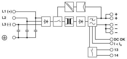
QUINT-PS/3AC Industrial Power Supply Block Diagram
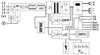
QUINT4-PS/3AC/24DC Industrial Power Supply Block Diagram
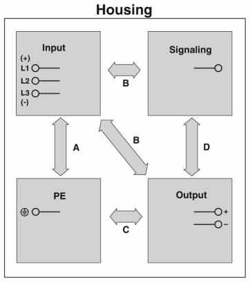
Schematische Darstellung
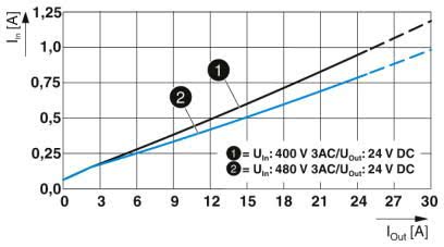
QUINT4-PS/3AC/24DC/10 Input current vs output current
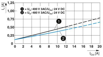
QUINT4-PS/3AC/24DC/20 Input current vs output current
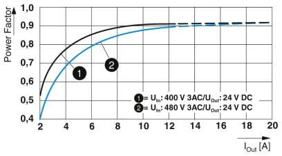
QUINT4-PS/3AC/24DC/10 Power factor diagram
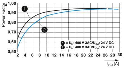
QUINT4-PS/3AC/24DC/20 Power factor diagram
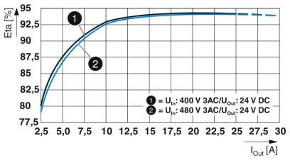
QUINT4-PS/3AC/24DC/10 Efficiency diagram
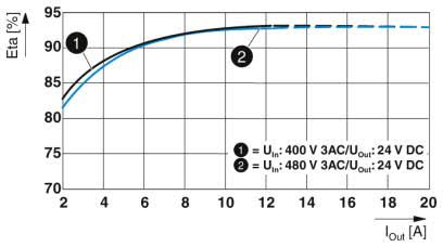
QUINT4-PS/3AC/24DC/20 Efficiency diagram
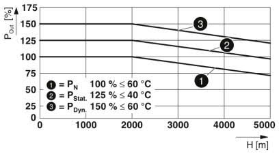
QUINT4-PS/3AC/24DC/10 Output power depending on the installation height
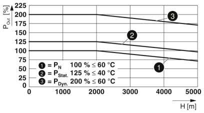
QUINT4-PS/3AC/24DC/20 Output power depending on the installation height
Klicken Sie eine Artikelnummer um Bestellinformationen einzusehen.
Produktbild
Beschreibung
Netzkabel & Artikelnummer

QUINT4-PS/3AC/24DC/10 Power Supply - QUINT power supply with free choice of output characteristic curve, SFB (selective fuse breaking) technology, and NFC interface, input: 3-phase, output: 24 V DC/10 A

QUINT4-PS/3AC/24DC/20 Power Supply - QUINT power supply with free choice of output characteristic curve, SFB (selective fuse breaking) technology, and NFC interface, input: 3-phase, output: 24 V DC/20 A

QUINT-PS/3AC/24DC/40 Power Supply - QUINT power supply for DIN rail mounting with SFB (Selective Fuse Breaking) Technology, input: 3-phase, output: 24 V DC/40 A

QUINT-PS/3AC/48DC/20 Power Supply - QUINT power supply for DIN rail mounting with SFB (Selective Fuse Breaking) Technology, input: 3-phase, output: 48 V DC/20 A


